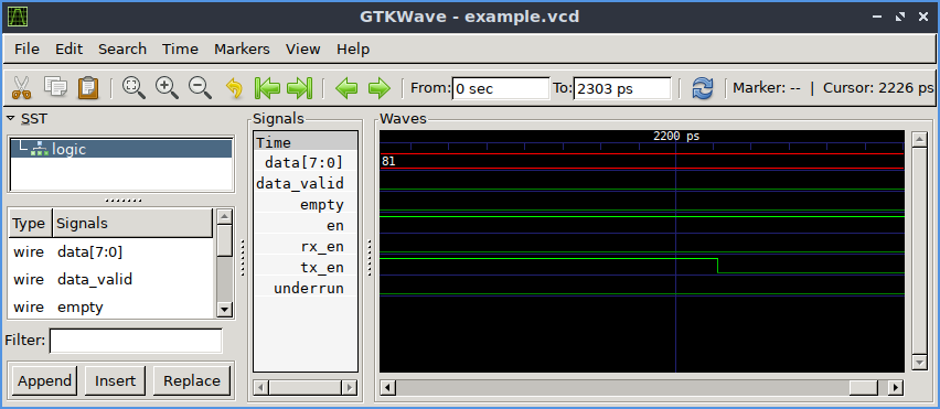
A waveform drawn with GTKWave
GTKWave is a VCD waveform viewer based on the GTK library. This viewer support VCD and LXT formats for signal dumps.
The home page for GTKWAVE is here.
Generating VCD/LXT files for GTKWAVE
Waveform dumps are written by the Icarus Verilog runtime program vvp.
The user uses $dumpfile and $dumpvars system tasks to enable waveform
dumping, then the vvp runtime takes care of the rest. The output is written
into the file specified by the $dumpfile system task. If the $dumpfile
call is absent, the compiler will choose the file name dump.vcd or dump.lxt, depending
on runtime flags.The example below dumps everything in and below the test module.
Example:
// Do this in your test bench

initial
 begin
    $dumpfile("test.vcd");
    $dumpvars(0,test);
 end
By default, the vvp runtime will generate VCD dump output. This is the default because it is the most portable. However, when using gtkwave, the LXT output format is faster and most compact. Use the "-lxt2" extended argument to activate LXT output. For example, if your compiled output is written into the file "foo.vvp", the command:
% vvp foo.vvp -lxt2 <other-plusargs>
will cause the dumpfile output to be written in LXT2 format. Absent any specific $dumpfile command, this file will be called dump.lxt, which can be viewed with the command:
% gtkwave dump.lxt
See also FAQ: How do I debug a Verilog design with Icarus
Here is a working example:
First, the design itself:
module non_overlapping_mealy (out, in, rst, clk);
output out;
input in, clk, rst;
reg out;
reg [1:0] state;
parameter s0=3'd0,
s1 = 3'd1,
s2 = 3'd2,
s3 = 3'd3,
s4 = 3'd4;
always @(posedge clk or negedge rst)
if (rst == 0) begin
state = s0;
out = 0;
end
else begin
case (state)
s0 : if (in == 0) begin
out = 0;
state = s0;
end
else begin
out = 0;
state = s1;
end
s1 : if (in == 0) begin
out = 0;
state = s2;
end
else begin
out = 0;
state = s0;
end
s2 : if (in == 1) begin
out = 0;
state = s3;
end
else begin
out = 0;
state = s0;
end
s3 : out = 0;
state = s4;
s4 : if (in == 1) begin
out = 0;
state = s0;
end
else begin
out = 1;
state = s0;
end
end
end
endmodule
Then the simulation file:
'timescale 1ns/1ps
module tb_mealy();
reg clk, rst, in;
wire out_non_overlapping, out_overlapping;
initial begin
clk = 0;
rst = 1;
in = 0;
repeat (10) rst = 0;
end
always #1 clk = ~clk;
always #15 in = $random;
non_overlapping_mealy u_non_overlapping_mealy (.in(in), .rst(rst), .clk(clk), .out(out_non_overlapping));
overlapping_mealy u_overlapping_mealy (.in(in), .rst(rst), .clk(clk), .out(out_overlapping));
initial begin
#1ms;
$finish;
end
endmodule
Compile it:
iverilog -o dsn counter_tb.v counter.v
Then run it:
vvp dsn
Then look at the test.vcd waveform:
gtkwave test.vcd &
Click on the 'test', then 'c1' in the top left box on GTKWAVE, then drag the signals to the Signals box.